Cango3D User Guide
Cango3D
Cango3D is a graphics library for the HTML5 canvas element which simplifies the drawing and animation of 3D shapes on the 2D canvas. The current version of Cango3D is 8v00, and the source code is available here Cango3D-8v00.js and the minified version may be downloaded here Cango3D-8v00-min.js.
New in Version 8
- The generic Obj3D has become a private Cango3D object. Its three derived types Path3D, Shape3D and Text3D, have each been given their own constructors.
- The predefined 'shapes3D' have been renamed 'shapeDefs3D' to avoid confusion with Shape3D object.
- The Cango3D 'tagShape' method has been dropped and replaced by the Group3D method 'tagFirstChild'.
- An object's 'soft' transform matrix is now automatically reset after rendering, the use of transform.reset method has been deprecated.
- The 'renderFrame' method has been dropped avoiding additional transforms being applied when waiting for the render to execute.
Architecture
Cango3D supports drawing just three basic objects path outlines, filled shapes and text. To draw any of these the application code first creates the corresponding Path3D, Shape3D or Text3D object. Path3D objects are rendered as outlines. Shape3D objects are always filled with their color shaded according to the location of the light source. Text3D objects are rendered in a stroked font with each character converted into a multi-segment 3D path. The 3D coordinates defining the path, shape or text outlines are stored as a property of the object, other properties define the position and appearance of the object when rendered to the canvas, such fill color, stroke color, font size and so on. They all have a centroid property, which is used in calculation of stacking order when multiple objects are rendered. Shape3D and Text3D are treated as flat panels they have a normal property used in calculating color shading (The restriction to co-planar coordinates is not enforced so 2D projections of genuine 3 dimensional shapes can be drawn).
'Hard' transform methods
Path3D, Shape3D, Text3D and Group3D have a set of common methods inherited from the generic 'Obj3D' object. Obj3D have a set of 'hard' transform methods, translate, rotate and scale. These methods make permanent changes to the object's outline coordinate definitions altering the path's offset, orientation and size. They are designed for construction more complex objects from component panels.
'Soft' Transform Methods
Obj3D have a transform property which has methods obj.transform.translate, obj.transform.rotate, obj.transform.revolve and obj.transform.scale. Each method creates a transform matrix that is applied to Obj3D's 'soft' transform matrix, which is initially the identity matrix which accumulates the effects of the transforms. The net transform matrix is applied to the coordinates when rendered. The Obj3D coordinates are multiplied by this net transform and the 2D projection of the resulting coordinates are rendered. The 'soft' transform matrix is then reset to the identity matrix, the objects' definition coordinates are not altered. The transform methods are designed for drag-and-drop and animation applications.
Complex structures are formed by maneuvering component objects and grouping them as a Group3D object. Group3D can have more Group3D as children as well as Obj3D so a family tree can be created to an arbitrary depth. Group3D also have the 'hard' and 'soft' matrix transform methods as Obj3D for maneuvering all their descendants as a single entity. Transforms applied to a Group3D are inherited by its children. Child objects may have transforms applied to them directly, these are combined with the inherited transform and the resulting net transform is applied to descendent Obj3D recursively.
Cango3D constructor
Syntax:
var cgo = new Cango3D(canvasID);
Description:
To start drawing an instance of the Cango3D graphics context must be created. This requires a canvas element to exist in the web page and for it to have a unique ID. Pass the canvas ID to the Cango3D constructor and the Cango3D object is returned.
Parameters:
canvasID:String - The 'id' attribute of the canvas object on which the Cango3D graphics context will draw.
Returns:
Cango3D object - An instance of the Cango3D graphics library which has all the following properties and methods.
Cango2D properties
| Property | Type | Description |
|---|---|---|
| ctx | CanvasRenderingContext2D | The raw canvas drawing context. This is available to access the more esoteric canvas capabilities. |
| aRatio | Number | Aspect ratio of the canvas element, the canvas width divided by canvas height. If the canvas is 300px wide and 200px high, cgo.aRatio = 1.5. |
Cango3D coordinate system methods
Syntax:
cgo.setWorldCoords3D(lowerLeftX, lowerLeftY, spanX);
Description:
Defines a world coordinate system for subsequent drawing operations with this graphics context. The world coordinate system sets translation and scaling factors to map world coordinate values to canvas pixel coordinates. The canvas is always in the X,Y plane. The coordinate system is right handed, the X axis is always +ve to the right, Y axis is +ve up the screen and Z axis is +ve out of the screen. X, Y and Z axes all have the same scale factor.
World coordinates are set by defining the coordinate values of the lower left corner of the canvas and the width of the canvas. Since the canvas has equal scaling factors in the X, Y and Z directions, setting the span of the canvas X dimension is sufficient to set all scaling factors. The X,Y coordinates of the lower left corner are sufficient to set the origin {0, 0, 0} of the coordinate system. The lower left Z coordinate value does not need to be specified as the canvas always in the X,Y plane (z=0).
Parameters:
lowerLeftX:Number - World X coordinate value of the lower left corner of the canvas.
lowerLeftY:Number - World Y coordinate value of the lower left corner of the canvas.
spanX:Number - The width of the canvas in world coordinates.
If setWorldCoords3D is called with no parameter passed, or not called at all, the world coordinate system is set to have the canvas lowerLeft=0,0 and spanX = 100.
Right Hand Cartesian coordinate system
Cango3D coordinate system is Right Hand Cartesian, with X values increasing to the RIGHT, Y increasing UP the screens and Z increasing OUT from the screen. The canvas lies in the XY plane at Z=0. The viewpoint is at some distance from the canvas along the Z axis, the current field-of-view angle sets the viewpoint distance.
Syntax:
cgo.setLightSource(x, y, z);
Description:
Defines a vector in 3D space starting at the origin and ending at {x:, y:, z:}. Shading of rendered Obj3D faces is determined by the dot product of the unit vector in the direction of the light source and the unit vector normal to the front face of the Obj3D. If no call is made to setLightSource the default value is {x:0, y:100, z:500}.
Parameters:
x:Number - X coordinate of the light source direction vector measured in world coordinates.
y:Number - Y coordinate.
z:Number - Z coordinate.
Syntax:
cgo.setFOV(deg);
Description:
Sets the Field Of View represented by calculating the location of the viewpoint at which the width of the canvas will subtend an angle of 'deg'. The viewpoint distance is used for all subsequent rendering on the canvas. The Field-Of-View will determine extent of the perspective distortion of an objects dimensions, values greater than 60° produce less realistic perspective effects, as result setFOV restricts the value of 'deg' to range 20° to 60°, a value of 45° is recommended. The calculation assumes the world coordinate origin is always on the canvas, if not the field of view is calculated as if the origin were on the edge of the canvas and the FOV should be set to smaller values to prevent undue distortion.
Parameters:
deg:Number - The angle subtended at the viewpoint by the width of the canvas, measured in degrees. The viewpoint distance along the Z axis is set to yield the requested Field-of-View. Angles greater than 60° or less than 20° are ignored.
Syntax:
var posObj = cgo.toPixelCoords3D(x, y, z);
Description:
This method converts the coordinates (x, y, z) of a point expressed in world coordinates to an object with {x:, y:, z:} properties that hold the raw canvas pixel coordinates of the point. The canvas pixel coordinates of the Cango3D context are set to be equal to the screen pixels when the graphics context is created, so 'toPixelCoords' always returns the canvas pixel coordinates which map 1 to 1 with screen pixels.
Parameters:
x, y, z:Number - X, Y, Z coordinates of a point measured in world coordinates.
Returns:
Object - An object with three properties:
x, y, z:Numbers - X, Y and Z coordinates of the point measured in canvas pixel coordinates.
Syntax:
var posObj = cgo.toWorldCoords3D(x, y, z);
Description:
This method converts the coordinates (x, y, z) of a point expressed in canvas pixels coordinates to an object with {x:, y:, z:} properties that hold the equivalent world coordinates of the point.
Parameters:
x, y, z:Number - X, Y, Z coordinates of a point measured in pixel coordinates.
Returns:
Object - An object with three properties:
x, y, z:Number - X, Y and Z coordinates of the point measured in current world coordinates of the cgo graphics context.
Obj3D: Path3D, Shape3D, Text3D
All objects drawn with Cango3D are composed of Obj3D. There are three types of Obj3D each a JavaScript object with its own constructor: Path3D, Shape3D and Text3D. All these constructors take a definition parameter which may be an outline path definition for Path3D and Shape3D or a string for Text3D objects. The constructors can take a second optional parameter that sets the initial values of properties. These objects are created independent of the Cango3D instance and have transforms applied and properties modified prior to rendering. These Obj3D once instantiated may be rendered and re-rendered without having to be re-constructed each time which is desirable in animations.
Most drawing starts with simple flat shapes, rectangles, circles Bezier curves etc. defined in the XY plane. All coordinates are of course 3 dimensional more complex objects are then built by applying 3D matrix transforms to these simple panels and grouping them into the more complex objects.
All Obj3D have methods which apply transforms to their initial definition. These are; obj.rotate, obj.scale and obj.translate. These are 'hard' transforms which permanently alter the definition of the object. All Obj3D also all have a 'transform' property whose methods make apply 'soft' ie. temporary transformations to the object as it is rendered. This 'soft' transform matrix is reset after the Obj3D is rendered.
Here are more details about each Obj3D type.
Path3D constructor
Syntax:
var obj = new Path3D(data[, options]);
Description:
Takes a 'data' parameter which is an array of Cgo3D format commands and their associated 3D coordinates and returns a Path3D object suitable for rendering by a Cango3D context.
Path definition data may be imported in 2D SVG format, possibly copied as a string from an SVG editor such as InkScape, or as an array in Cgo2D format, which is just the SVG single letter commands with their coordinate pairs stored as an array. These strings or arrays of 2D data can use the entire SVG path command set. The paths they represent will of course be two dimensional and must be converted to the Cgo3D format before being passed to the Path3D constructor. The utility provided to do this conversion is svgToCgo3D.
To simplify defining the most common shapes Cango3D provides the shapeDefs3D utility. The shapeDefs3D methods create a Cgo3D data array representing the outline path of many commonly used shapes. The methods take dimension parameters such as the width and height of the ellipse, the diameter of the circle, side length of a square etc.
When rendered the Path3D outline will be drawn with a line width set by 'lineWidth' (in pixels) or 'lineWidthWC' in world coordinates. The line color is set by its 'strokeColor' property. If these properties has not been set explicitly by the user code then the default value from the Cango3D context used to render the Path3D will be used.
Parameters:
data: Array - A JavaScript array of Cgo3D command letters and associated coordinates defining the outline path. The Cgo3D syntax is a sub-set of the SVG path drawing command set, restricted to M (move), L (straight line), Q (Quadratic Bezier curve) and C (Cubic Bezier curve) commands (see Cgo3D syntax).
options: Object - An optional JavaScript object containing key-value pairs to set the properties of the Path3D object returned. The keys and value ranges are described in the setProperty method.
Example
The following line of code will create a 'Path3D' object. When rendered 'obj' will be drawn as a square with width and height 4 units in the world coordinate units. The outline will be 2 pixels wide and colored 'red'.
var obj = new Path3D(['M',2,-2,0, 'l',0,4,0, -4,0,0, 0,-4,0, 'z'], {
  lineWidth: 2,
  strokeColor: 'red'});
Path3D properties
| Property Name | Type | Range / Description |
|---|---|---|
| strokeColor | CSS Color | see Colors |
| lineWidthWC | Number (World Coordinates) | > 0 |
| lineWidth | Number (pixels) | > 0 |
| lineCap | String | 'butt', 'round', 'square' |
Path3D methods
Path3D objects along with Shape3D and Text3D inherit all the Obj3D methods described below.
Shape3D constructor
Syntax:
var obj = new Shape3D(data[, options]);
Description:
Takes a 'data' parameter which is an array of Cgo3D format commands and their associated 3D coordinates and returns a Shape3D object suitable for rendering by a Cango3D context.
Shape outline path definition data may be imported in 2D SVG format, possibly copied as a string from an SVG editor such as InkScape, or as an array in Cgo2D format which is just the SVG single letter commands with their coordinate pairs stored as an array. These strings or arrays of 2D data can use the entire SVG path command set. The paths they represent will of course be two dimensional and must be converted to the Cgo3D format before being passed to the Shape3D constructor. The utility provided to do this conversion is svgToCgo3D.
To simplify defining the most common shapes Cango3D provides the shapeDefs3D utility. The shapeDefs3D methods create a Cgo3D data array representing the outline path of many commonly used shapes. The methods take dimension parameters such as the width and height of the ellipse, the diameter of the circle, side length of a square etc.
When rendered, the outline path will be closed (if not already closed) and the Shape3D will be filled. If the normal to the surface is facing toward the viewpoint, it is filled with color value of its 'fillColor' property, if facing away it is filled with 'backColor'. If either of these properties have not been set explicitly by the user code then the default values from the Cango3D context used to render the Shape3D will be used.
Parameters:
data: Array of Cgo3D data - The Cgo3D array holds command letters and associated coordinates defining the shape outline. The full SVG set of commands is supported (see Cgo3D syntax).
options: Object - This object may contain key-value pairs to pre-set the properties of the object returned. The keys and value restrictions are identical to those described in the setProperty method.
Example
The following line of code will create a Shape3D object and then scale its size. When rendered 'obj' will be drawn as a square with width and height 4 units in the world coordinates of the Cango3D context used to render it.
var obj = new Shape3D(['M', 2,-2,0, 'l',0,4,0, -4,0,0, 0,-4,0, 'z'], {fillColor: 'pink'});
Shape3D properties
| Property Name | Type | Range / Description |
|---|---|---|
| fillColor | CSS Color or gradient | see Colors |
| backColor | CSS Color | see Colors |
| backHidden | Boolean | true or false |
Shape3D methods
Shape3D objects along with Path3D and Text3D inherit all the Obj3D methods described below.
Text3D constructor
Syntax:
var obj = new Text3D(str[, options]);
Description:
Creates a Text3D object comprising the set of straight line segments forming each character in the string 'str'. The characters are rendered in the Cango3D font, which uses characters from the Hershey stroke font. The Cango3D character set comprises 104 characters from the standard ASCII character set and 52 special characters, the upper and lower case Greek alphabet and some mathematical symbols. Special characters are generated by inserting their corresponding Unicode into the text string using the '\uXXXX' format.
The text characters are scaled to be 'pxlSize' pixels (independent of the world coordinate scaling). The line width used when rendering is set by the fontWeight property. The 'lorg' property sets the drawing origin, the point within the text bounding box that will the reference point for translating, rotating or scaling the text.
Parameters:
str: String - The text string to be converted to 3D path segments suitable for 3D rendered to the canvas.
options: Object - This object may contain key-value pairs to pre-set the properties of the Text3D object returned. The keys and value restrictions are identical to those described in the setProperty method.
Example
var obj = new Text3D("Hullo World", {
  fillColor: "blue",
  fontSize: 28,
  lorg:5 });
This code snippet will create a Text3D object when rendered, the text "Hullo World" will be drawn onto the canvas. The fontSize will be 28 pixels, fontWeight and fontFamily will be the default values of Cango3D context used to render the Text3D as these properties have not been explicitly set. The text will be colored blue. The lorg 5 value will result in drawing origin being set at the center of the text bounding box. When rendered the drawing origin will be placed at the world coordinate origin (0,0) unless a translate transform is applied to the Text3D prior to rendering.
Text3D properties
| Property Name | Type | Range / Description |
|---|---|---|
| strokeColor | CSS Color | Specifies border color, see Colors |
| border | Boolean | true or false |
| fontFamily | String | CSS fontFamily definitions |
| fontSize | Number (pixels) | - |
| fontWeight | Number | 100..900 |
| lorg | Number | 1..9 (see lorg) |
Text3D methods
Text3D objects along with Path3D and Shape3D inherit all the Obj3D methods described below.
Obj3D methods
Obj3D have the following methods to adjust their 3D coordinate definitions, obj.translate, obj.rotate and obj.scale.
These methods apply 'hard' transforms to the coordinates defining the object's outline path, so all future rendering will show the effects of these changes.
Drag-n-Drop capability can be enabled on any Obj3D by calling the obj.enableDrag(grab, drag, drop) method of the object, passing as parameters the callback functions that should be executed when 'mousedown', 'mousemove' and 'mouseup' events occur. The Obj3D drag-n-drop can be disabled using obj.disableDrag.
To calculate shading for Shape3D, a 'normal' vector, perpendicular to the surface is maintained as a Shape3D property. If a shape is drawn in the XY plane and the outline path is defined by traversing the nodes counter-clockwise (CCW) then the normal will point out of the canvas. If the outline path is traversed clockwise (CW) then the normal will point into the canvas and only the back of the panel is seen. If a path is found to have been defined such that the calculated normal faces in the opposite direction than was intended, rather than recalculate the path definition traversing the nodes in the opposite sense, the obj.flipNormal method is provided to flip the normal by 180°.
Obj3D method details
Syntax:
obj.enableDrag(grabCallback, dragCallback, dropCallback);
Description:
This method takes as parameters the user defined functions to be called mousedown, mousemove or mouseup (or mouseout) events. It saves a reference to 'obj' in the array of objects to be checked when a mousedown event occurs on the canvas.
Once an object is enabled, the Cango3D 'mousedown' event handler will check if the mouse event occurred within the outline of the object. If it did, then the object's grab event handler is called, this assigns handlers for subsequent 'mousemove' and 'mouseup' events and then calls the user 'grabCallback' function. On subsequent mousemove or mouseup events, the object's event handlers will update the cursor coordinates and call the 'dragCallback' or 'dropCallback' functions. For every drag callback ie. every mousemove event, the current world coordinates of the cursor are always passed to the callback functions as an object with x,y,z properties. The cursor location is a point on the canvas which is always in the XY plane, therefore the z property of the cursor location will always be 0.
Drag-n-drop callbacks often need to know the drawing origin and the cursor offsets when the grab occurred. To simplify writing grab, drag and drop functions, the callbacks are executed in the scope of a Drag3D object which has properties to supply these values. All the handy properties in scope of the handlers are listed in the Drag3D section below.
Parameters:
grabCallback: Function or null - This function to be called when a 'mousedown' event occurs within the outline of 'obj'. An object containing the current cursor world coordinate position is the only parameter passed when the function is called. The cursor position object has x: and y: properties.
dragCallback: Function or null - This function to be called when a 'mousemove' event occurs after the mouse down event has occurred with the outline of 'obj'. An object containing the current cursor world coordinate position is the only parameter passed when the function is called. The cursor position object has x: and y: properties.
dropCallback: Function or null - This function to be called when a mouseup or mouseout event occurs after the mouse down event. An object containing the current cursor world coordinate position is the only parameter passed when the function is called. The cursor position object has x: and y: properties.
Example
As an example of the enableDrag method, here is a code snippet that simply moves text with the cursor:
function txtSimple(g)
{
  var txt1;

  function dragTxt(mousePos)
  {
    var newPos = {x:mousePos.x-this.grabOfs.x,
                  y:mousePos.y-this.grabOfs.y,
                  z:mousePos.z-this.grabOfs.z};
    txt1.transform.translate(newPos.x, newPos.y, newPos.z);
    txt1.render();
  }

  g.clearCanvas();
  g.setWorldCoords3D(-400, -200, 800);
  g.setViewpointDistance(500);

  txt1 = new Text3D("Hullo World", 'green', 20, 700, 5);
  txt1.enableDrag(null, dragTxt, null);
  txt1.render();
}
Syntax:
obj.disableDrag();
Description:
Sets the obj.dragNdrop property to 'null' and removes the reference to obj from the array of objects to be checked for a hit on mousedown events.
Parameters:
none
Syntax:
obj.setProperty(propertyName, val);
Description:
Sets the values for various Path3D, Shape3D or Text3D properties. The property whose value is to be set is specified by the string 'propertyName' this string is not case sensitive and may take the values set out in column 1 of the table below.
The new value is passed as 'value'. The value must be of an appropriate type and fall within the useful range of values for the property, and the types are listed in column 2 and range of values is listed in column 3. If the property is not one of the string values listed or the value is an incorrect type then the call is ignored and the current value remains unaltered.
Each Cango3D context holds default values for all the properties needed by the render method. So if the property has not been set prior to rendering the default value set in the Cango3D context used to render the Obj3D will be used. Cango3D property defaults are set by the cgo.setPropertyDefault method.
| Name | Type | Range |
|---|---|---|
| fillColor | CSS Color | valid RGBA color |
| strokeColor | CSS Color | valid RGBA color |
| backColor | CSS Color | valid RGBA color |
| lineWidth | Number (pixels) | - |
| lineCap | String | 'butt', 'round', 'square' |
| fontSize | Number (pixels) | - |
| fontWeight | Number | 100..900 |
| lorg | Number | 1..9 (see lorg) |
Parameters:
propertyName: String- The name of the Obj3D property the value of which is to be set. It must be one of the strings listed in column 1 of the table above. The string value is not case sensitive.
value: (various types) - The new value for the property. Its type should match the type listed in column 2 of the table and its range should fall with the range set out in column 3 of the table above.
Syntax:
obj.flipNormal();
Description:
If an Obj3D previously defined and has the calculated normal the wrong way, so the back surface is shown in a default color instead of the correct colored front, then the Obj3D method flipNormal called on the object will flip the normal to the opposite direction.
Parameters:
None
Syntax:
obj.rotate(vx, vy, vz, theta);
Description:
Each 3D point defining the Obj3D 'obj', its, centroid and normal are transformed to have its position rotated by and angle 'theta' degrees about the axis defined by the vector (vx, vy, vz). The new coordinate values over-write the old coordinates, so whenever the object is re-drawn it will have the net effect of this rotation as it reference position. This 'rotate' method should be used in positioning component panels in construction of multi-panel 3D object, not for animation.
Parameters:
vx, vy, vz:Points - The x, y, and z components of a vector from the origin to the point vx,vy,vz. The vector can be of any length (it will be converted to a unit vector before use). The vector defines the axis, about which all points of the object will be rotated. The angle 'theta' is measured in degrees, +ve anti-clockwise when the vector is pointing at you (right hand rule).
theta:Number - The rotation angle measured in degrees, +ve in the direction your right hand fingers curl if your right thumb is pointing in the direction of the vector (right hand rule).
Syntax:
obj.scale(s);
Description:
Each 3D point defining the outline path of 'obj', its centroid and normal have their X, Y and Z coordinates multiplied by the scale factor 's'. The effect of this is to expand or contract the size of the object with the expansion or contraction centered on the drawing origin (0, 0, 0). The new coordinate values over-write the old coordinates, so when ever the object is re-drawn it will maintain this new size. This 'scale' method should be used in positioning component panels in construction of arrays of Obj3D forming a multi-panel 3D object, not for animation.
Parameters:
s:Number - The scale factor, greater than 0, by which the object's size in to be increased or decreased.
Syntax:
obj.translate(x, y, z);
Description:
Each 3D point defining the outline path, centroid and normal of 'obj', has the factors, 'x', 'y' and 'z' added to their respective coordinates. The effect of this is to move the object relative to its drawing origin. The new coordinate values over-write the old coordinates, so when ever the object is re-drawn it will have this displacement from its drawing origin. This 'translate' method should be used in positioning component panels in construction of arrays of Obj3D forming a multi-panel 3D object, not for animation.
Parameters:
x:Number - The X coordinate offset measured in world coordinates to be added to all drawing command coordinates.
y:Number - The Y coordinate offset.
z:Number - The Z coordinate offset.
Syntax:
obj.transform.rotate(vx, vy, vz, degs);
Description:
Adds a rotate matrix to the transforms to be applied to the object when rendered. The object will be rotated by 'degs' degrees about the axis defined by a vector starting object's drawing origin and parallel to the vector vx, vy, vz. This rotation is independent of any transform.translate calls that may have moved the drawing origin from the world coordinate origin, like the earth rotating on it's axis.
Parameters:
vx, vy, vz: Points - The x, y, and z components of a vector from the origin to the point vx,vy,vz. The vector can be of any length (it will be converted to unit length before use). The vector defines the axis, about which all points of the object will be rotated. The transform.rotate is applied before any transform.translate, so the axis of rotation is through the drawing origin rather than the world coordinate origin.
degs:Number - the angle by which this transform will rotate an object. The angle 'degs' is measured in degrees, +ve anti-clockwise if the axis vector is pointing at you (right hand rule).
transform.scale
Syntax:
obj.transform.scale(scl);
Description:
Adds a scale matrix to the transforms to be applied to the object when rendered. The object's coordinates will be scaled by a factor 'scl'. The objects dimensions enlarge or contract centered on the object's drawing origin, independent of any transform.translate that may have been applied.
Parameters:
scl: Number - A number, greater than 0, by which the objects dimensions relative to it's drawing origin are scaled.
Syntax:
obj.transform.translate(x, y, z);
Description:
Adds a translation matrix to the transforms to be applied to the object when rendered. The object's drawing origin will be offset from its current location by x, y and z world coordinate units in the X direction, Y direction and Z direction respectively.
Parameters:
x, y, z: Numbers - The distance in the X, Y and Z directions respectively that the object will be moved relative to the world coordinate origin.
Syntax:
obj.transform.revolve(vx, vy, vz, degs);
Description:
Adds a revolve matrix to the transforms to be applied to the object when rendered. The object will be revolved by 'degs' degrees about the axis defined by the vector starting from the world coordinate origin (not the object's drawing origin) and ending at the location vx, vy, vz. If no transform.translate has been applied prior to this method being called, transform.revolve behaves identically to transform.rotate, since the object drawing origin has not been moved from the world coordinate origin, but if the object has been translated, this method revolves the object around the world coordinate origin now some distance from the object, like the earth revolving around the sun.
Parameters:
vx, vy, vz: Points - The x, y, and z components of a vector from the origin to the point vx,vy,vz. The vector can be of any length (it will be converted to unit length before use). The vector defines the axis, about which all points of the object will be revolved.
degs: Number - the angle by which this transform will revolve an object. The angle 'degs' is measured in degrees, +ve anti-clockwise if the axis vector is pointing at you (right hand rule).
Group3D
Group3D can be created using the Group3D constructor. The objects to be grouped are passed as parameters. Objects can be added later using the Group3D.addObj method.
The Group3D object has the property 'children', an array containing Obj3D and/or Group3D. Objects are added to Group3D's 'children' array by the addObj method which can take Obj3D, Group3D or arrays of them as parameters. Children can be removed by the deleteObj method.
Group3D also have several methods that can be applied to all their children recursively: grp.translate, grp.rotate and grp.scale.
The translate, rotate and scale methods recursively apply 'hard' transforms to the coordinates of the Group3D's children, so all future rendering will show the effects of these changes. These methods are useful in creating more complex objects by maneuvering the component Obj3D. These are not suitable for animation.
All the children of a Group3D can be 'drag-n-drop' enabled or disabled with a call to the Group3D methods, grp.enableDrag and grp.disableDrag.
There is one more method can create a complex Group3D comprising many Obj3D in a single call, cgo.objectOfRevolution3D. It takes a path specified as an array of Cgo3D data representing a profile and forms a 3D object by rotating the profile in steps about the Y axis forming a 3D object with segments like an orange.
Group3D constructor
Syntax:
var obj = new Group2D(...);
Description:
Creates a Group3D object with a 'children' array property which hold Obj3D and other Group3D. The Group3D object has methods to apply transforms to children, and recursively apply them to the children of child Group3D. The objects forming the Group3D's children may be passed as parameters, either individual Obj3D or Group3D or arrays of either. More objects can be added to the group after creation, by using the addObj method.
Parameters:
. . . :Objects, Group2D or arrays or either - The 'arguments' property is parsed to extract all Obj3D and Group3D and they are added to the grp.children array in sequence left to right.
Group3D method details
addObj
Syntax:
grp.addObj(...);
Description:
The method adds Obj3D or Group3D to the Group3D, grp. The arguments can be single Obj3D or Group3D or arrays of either. The array structure is discarded and the individual Obj3D or Group3D are added to the grp.children array.
Parameters:
. . . :Obj3D, Group3D or arrays or either - The arguments variable is parsed to extract all Obj3D and Group3D and they are added to grp's children array.
deleteObj
Syntax:
grp.deleteObj(obj);
Description:
If 'obj' is a child of the Group3D 'grp' then it is removed from the array of children.
Parameters:
obj:Obj3D or Group3D - The child to be removed from the Group3D.
Syntax:
Syntax:
grp.enableDrag(grabCallback, dragCallback, dropCallback);
Description:
Calls the Obj3D.enableDrag method on all grp's Obj3D children, and also calls the method on all the Obj3D children of grp's Group3D children and so on recursively for its descendants. The three user defined call back functions 'grabCallback', 'dragCallback', 'dropCallback' are passed to the Obj3D.enableDrag method.
Drag-n-drop callbacks often need to know the drawing origin and the cursor offsets when the grab occurred. To simplify writing grab, drag and drop functions, the callbacks are executed in the scope of a Drag3D object which has properties to supply these values. All the handy properties in scope of the handlers are listed in the Drag3D section below.
Parameters:
grabCallback:Function or null - This function to be called when a 'mousedown' event occurs within the outline of the grp's descendent Obj3D. An object containing the current cursor world coordinate position is the only parameter passed when the function is called. The cursor position object has x: and y: properties.
dragCallback:Function or null - This function to be called when a 'mousemove' event occurs after the mouse down event has occurred with the outline of the grp's descendent Obj3D. An object containing the current cursor world coordinate position is the only parameter passed when the function is called. The cursor position object has x: and y: properties.
dropCallback:Function or null - This function to be called when a mouseup or mouseout event occurs after the mouse down event. An object containing the current cursor world coordinate position is the only parameter passed when the function is called. The cursor position object has x: and y: properties.
Syntax:
grp.disableDrag();
Description:
Sets the grp.dragNdrop property to 'null' and removes the reference to grp's children from the array of objects to be checked for a hit on mousedown events.
Parameters:
none
Syntax:
grp.tagFirstChild(tagObj, xOfs, yOfs);
Description:
Requires the first child of the Group3D 'grp' to be a Shape3D, if so, this method inserts the Obj3D 'tagObj' into the Group3D children array as the second element. The centroid of 'tagObj' is set to be a copy of the centroid of the first child (the Shape3D object) so that any transformations the group suffers will not affect the sorted order of the group when rendered. Since they have the same centroid and the Shape3D is added as the first child, it will always be drawn first and the 'tagObj' will always be rendered in front. The 'backHidden' property of the 'tagObj' is set 'true' so if it is facing away from the viewpoint the 'tagObj' will not be rendered and only the back of the first child will be seen. Multiple tags may be added to a shape object by multiple calls to the method. Tag objects may be removed from the group using the Group3D.deleteObj method.
Parameters:
tagObj: Obj3D - A Text3D, Path3D or Shape3D ideally flat (essentially a 2D drawing) to be always drawn together with and in front of the Shape3D first child of the Group3D.
xOfs, yOfs: Numbers - X and Y offsets added to all the coordinates of the 'tagObj' to position its drawing origin with respect to the shape's drawing origin.
Syntax:
grp.rotate(vx, vy, vz, theta);
Description:
Calls the Obj3D.rotate method on all grp's Obj3D children, and also calls the method on all the Obj3D children of grp's Group3D children and so on recursively for its descendants. This 'rotate' method should be used in positioning the Group3D to form yet larger groups, not for animation.
Parameters:
vx, vy, vz:Points - The x, y, and z components of a vector from the origin to the point vx,vy,vz. The vector can be of any length (it will be converted to a unit vector before use). The vector defines the axis, about which all points of the object will be rotated. The angle 'theta' is measured in degrees, +ve anti-clockwise when the vector is pointing at you (right hand rule).
theta:Number - The rotation angle measured in degrees, +ve in the direction your right hand fingers curl if your right thumb is pointing in the direction of the vector (right hand rule).
scale
Syntax:
grp.scale(s);
Description:
Calls the Obj3D.scale method on all grp's Obj3D children, and also calls the method on all the Obj3D children of grp's Group3D children and so on recursively for its descendants. This 'scale' method should be used in positioning the Group3D to form yet larger groups, not for animation.
Parameters:
s:Number - The scale factor, greater than 0, by which the descendant object's size in to be increased or decreased.
Syntax:
grp.translate(x, y, z);
Description:
Calls the Obj3D.translate method on all grp's Obj3D children, and also calls the method on all the Obj3D children of grp's Group3D children and so on recursively for its descendants. This 'translate' method should be used in positioning the Group3D to form yet larger groups, not for animation.
Parameters:
x, y, z:Numbers - The X, Y, Z coordinate offsets measured in world coordinates to be added to all drawing command coordinates.
Syntax:
obj.transform.rotate(vx, vy, vz, degs);
Description:
Adds a rotate matrix to the transforms to be applied to the groups descendent Obj3D when rendered. The transform matrix is applied to all the children of the Group3D and to the children of any Group3D children recursively. Each Obj3D will be rotated by 'degs' degrees about the axis defined by a vector starting object's drawing origin and parallel to the vector vx, vy, vz. This rotation is independent of any transform.translate calls that may have moved the drawing origin from the world coordinate origin, like the earth rotating on it's axis.
Parameters:
vx, vy, vz:Points - The x, y, and z components of a vector from the origin to the point vx,vy,vz. The vector can be of any length (it will be converted to unit length before use). The vector defines the axis, about which all points of the object will be rotated. The transform.rotate is applied before any transform.translate, so the axis of rotation is through the drawing origin rather than the world coordinate origin.
degs:Number - the angle by which this transform will rotate an object. The angle 'degs' is measured in degrees, +ve anti-clockwise if the axis vector is pointing at you (right hand rule).
transform.scale
Syntax:
obj.transform.scale(scl);
Description:
Adds a scale matrix to the transforms to be applied to the groups descendent Obj3D when rendered. The transform matrix is applied to all the children of the Group3D and to the children of any Group3D children recursively. Each Obj3D's coordinates will be scaled by a factor 'scl'. The objects dimensions enlarge or contract centered on the object's drawing origin, independent of any transform.translate that may have been applied.
Parameters:
scl:Number - A number, greater than 0, by which the objects dimensions relative to it's drawing origin are scaled.
Syntax:
obj.transform.translate(x, y, z);
Description:
Adds a translate matrix to the transforms to be applied to the groups descendent Obj3D when rendered. The transform matrix is applied to all the children of the Group3D and to the children of any Group3D children recursively. Each Obj3D's drawing origin will be offset from its current location by x, y and z world coordinate units in the X direction, Y direction and Z direction respectively.
Parameters:
x, y, z:Numbers - The distance in the X, Y and Z directions respectively that the object will be moved relative to the world coordinate origin (0,0).
Syntax:
obj.transform.revolve(vx, vy, vz, degs);
Description:
Adds a revolve matrix to the transforms to be applied to the groups descendent Obj3D when rendered. The transform matrix is applied to all the children of the Group3D and to the children of any Group3D children recursively. Each Obj3D's coordinates will be revolved by 'degs' degrees about the axis defined by the vector starting from the world coordinate origin (not the object's drawing origin) and ending at the location vx, vy, vz. If no transform.translate has been applied prior to this method being called, transform.revolve behaves identically to transform.rotate, since the object drawing origin has not been moved from the world coordinate origin, but if the object has been translated, this method revolves the object around the world coordinate origin now some distance from the object, like the earth revolving around the sun.
Parameters:
vx, vy, vz: Points - The x, y, and z components of a vector from the origin to the point vx,vy,vz. The vector can be of any length (it will be converted to unit length before use). The vector defines the axis, about which all points of the object will be revolved.
degs: Number - the angle by which this transform will revolve an object. The angle 'degs' is measured in degrees, +ve anti-clockwise if the axis vector is pointing at you (right hand rule).
Rendering
Cango3D has just one method to draw Obj3D onto the canvas; cgo.render.
render takes a single Group3D or Obj3D as a parameter to be rendered to the canvas. In the case of Group3D, all the descendant Obj3D are rendered. All matrix transforms that have been accumulated by any of the Group3D or Obj3D in the family tree are propagated down the family tree structure to determine the final positions of the Obj3D. The 3D objects are depth sorted are projected into 2D and then rendered to the canvas most distant rendered first. Once all the Obj3D are rendered their 'soft' transform matrices are reset to the identity matrix.
Cango3D method details
Syntax:
cgo.render(obj, ...);
Description:
This method renders an Obj3D or all the Obj3D descendants of the Group3D, onto the canvas. By default the render method first clears the canvas. Two optional string parameters are recognised, 'noclear', which will prevent the current drawing on the canvas from being cleared and 'wireframe' which will prevent the Shape3D being filled with color, just their outline will be drawn.
The 'render' method applies all the object's accumulated transform matrices to form a net transform matrix which is applied to all the coordinates of 'obj' if it an Obj3D, or to descendant children if 'obj' is a Group3D. 'render' then sorts the Group3D's into the order that they will be drawn, based on distance of the Groups3D's centroid from the viewpoint, most distant (smallest Z coordinate value) will be drawn first. The all the descendant Obj3D within each group are sorted among themselves. All coordinates of the Obj3D are then projected from 3D to 2D to create the native 2D canvas draw commands which are then drawn onto the canvas.
Parameters:
obj: Obj3D or Group3D - The object or group of objects to be rendered to the canvas.
. . . : Option Strings - The strings 'noclear' and 'wireframe' may be passed as parameters in any order. 'noclear' inhibits the 'clearCanvas' call prior to rendering. 'wireframe' which will inhibit the color filling of Shape3D.
Syntax:
cgo.clearCanvas(fillColor);
Description:
Clears the canvas, deleting all drawing. The canvas may be optionally filled with the color 'fillColor. If 'clearCanvas' is called with no 'fillColor' parameter, then the canvas is cleared back to its background color. The background-color may be set be in the CSS code of the host page. Listening for mousedown events on any draggable objects is canceled.
Parameters:
none
Saving 3D objects to a file
Applications don't need to include all the object creation and positioning code every time they are run. Completed Obj3D or Group3D can have their defining properties converted to a JSON string, which can be saved to a file using the method cgo.Obj3DtoJSON and retrieved using cgo.JSONtoObj3D.
Obj3DtoJSON generates a JSON string describing an object or group. JSONtoObj3D converts the JSON parsed string back to the original group of objects. Code to save the JSON string to a file is beyond the scope of this library, but one handy technique is to save the string returned by Obj3DtoJSON as the 'innerHTML' property of an element on the HTML page, then, when the JSON string is displayed in the browser, copy and paste it into a text editor that has full file system access so the editor can save the string to disk as a '.json' file.
Cango3D Utility methods
Cango3D has several utilities methods to configure the 3D display environment, such as cgo.clearCanvas, cgo.setLightSource etc. All the methods are described in the reference sections below.
Cango3D method details
Syntax:
var obj = cgo.JSONtoObj3D(jsonData);
Description:
This method converts the JavaScript Objects or Arrays returned from JSON.parse(), into and Obj3D or Group3D. The data will come from parsing a JSON string, loaded from a previously saved file. This JavaScript data will contain Cgo3D format outline path definitions along with fillColor and strokeColor etc. to re-create the objects previously encoded into the file.
Parameters:
jsonData:JavaScript Objects and Arrays - This method expects the objects and arrays to be in the Cango3D JSON format.
Returns:
Obj3D or Group3D objects - Objects encapsulating the commands and various properties to re-create the originals.
Syntax:
var jsonStr = cgo.Obj3DtoJSON(obj, nameStr);
Description:
Obj3DtoJSON encodes the outline path definitions, colors and type etc. of an Obj3D or Group3D into a JSON format string. The returned JSON format string can be saved to a file for later re-loading to re-create the objects using the JSONtoObj3D utility. The 'nameStr' is optional, if present it will be saved as top level property 'name'.
Parameters:
obj:Obj3D or Group3D object - This method recursively parses the tree of objects from the root 'obj' into a JSON string. The string returned holds the various data such as outline path description, type, colors. The output is in the Cango3D JSON format.
nameStr:String - A user defined string which will be saved as the value of the property 'name'. If 'nameStr' is undefined then the default string 'Object1' will be saved as the 'name' property (see Cango3D JSON examples).
Returns:
JSON String - JSON format string containing sufficient data describing 'obj' to reconstruct it.
Syntax:
var obj = cgo.objectOfRevolution3D(path, xOffset, segments, fillColor, backColor, straight);
Description:
Generates a Group3D holding an array of Obj3D representing a multi-panel 3D object formed by revolving the profile specified by the 'path' parameter, about the Y axis. An xOffset may be applied to all coordinates to position the profile the required distance from the Y axis, this is usually required if the profile has been copied from an SVG editor. The path is then revolved by 360 degrees about the Y axis in 'segments' number of steps. At each step multiple Obj3D panels are formed from the corresponding draw commands of the path forming the sides of the panel and top and bottom are joined by circular arcs (by default) or straight lines if the 'straight' parameter evaluates to 'true'. The array of panels forming the Object of Revolution are added to new Group3D object which is returned.
Parameters:
data:Array or String - An array or string containing in Cgo3D format of single letter SVG drawing commands followed by x,y,z coordinate triplets, all z components are assumed to be 0. The first command must be 'M' followed by a coordinates specifying the x,y,z values of the starting point of the path. This is followed by commands specifying line segments. The path should be simple starting from the top of the profile (maximum Y coordinate) and monotonically decreasing to the bottom, all points should have +ve X coordinates (after xOffset has been added).
If the path is passed as a String, it is assumed to have been copied from and SVG editor such as Inkscape. The Y coordinates will be flipped to match the Cango3D convention of Y coordinates +ve up the screen.
xOffset:Number - An offset added to all X coordinates of the profile to position the profile with respect to the Y axis.
segments:Number - Specifies the number of segments, the 360 degree rotation will be divided by. The object is created like segments of an orange. The larger the number of segments the smoother the color gradations will be on the final shape but the slower it will be to render.
fillColor:String - The fill color to be used when the normal of a panel faces the viewpoint. The color may be expressed in any of the CSS color formats, see Colors notes for details. If 'fillColor' parameter is omitted or null, then the current paint color is used.
backColor:String - The fill color to be used when the normal of a panel faces away from the viewpoint. The color may be expressed in any of the CSS color formats, see Colors notes for details. If 'backColor' parameter is omitted or null, then the current fillColor is used. For closed shapes, where the back faces are never seen, this should be set to 'transparent'.
straight:Boolean - An optional boolean value, if true, then the sections of adjacent profiles are joined by straight lines rather than the default circular arcs.
Returns:
Group3D - the children of the group comprise the panels forming the 3D object.
Syntax:
cgo.setPropertyDefault(propertyName, val);
Description:
Sets the default values for various system properties. The property whose default is to be set is specified by the string 'propertyName' this string is not case sensitive and may take the values set out in column 1 of the table below.
The new default value is passed as 'value'. The value is restricted to be within the range of values appropriate to the property. If the property is not one of the string values listed or the value is an incorrect type or outside the reasonable range of values then the call is ignored and the current default value remains unaltered.
If no call is made to 'setPropertyDefault' for a particular property, then the property value remains at its system default value listed in column 4.
| Name | Type | Range | Default |
|---|---|---|---|
| backgroundColor | CSS Color | - | set by canvas element style |
| fillColor | CSS Color | - | 'rgba(128, 128, 128, 1.0)' |
| strokeColor | CSS Color | - | 'rgba(0, 0, 0, 1.0)' |
| strokeWidth | Number (pixels) | - | 1 |
| lineCap | String | 'butt', 'round', 'square' | 'butt' |
| fontSize | Number (points) | - | 10 |
| fontWeight | Number | 100..900 | 400 |
Parameters:
propertyName:String- The name of the property whose default value is to be set. It must be one of the strings listed in column 1 of the table above. The string value is not case sensitive.
value- The new default value for the property. Its type should match the type listed in column 2 of the table above and the range of values must fall within the range listed in column 3.
Global utility methods
Both Obj3D and Group3D have a 'transform' property which is an object with the following methods:
Syntax:
var degs = calcIncAngle(p1, p2, p3);
Description:
Calculates the included angle between the vectors from p1 to p2 and p1 to p3. If A is the vector defined as p2 - p1, and B is the vector p3 - p1, then the included angle (less than 180°) between A and B will be returned. The sign may be determined from the cross product A×B direction (determined from right hand rule). The direction of the positive angle is counter-clockwise when the cross-product is pointing at you.
Parameters:
p1:Object {x:, y: z:} - A point in 3D space which is taken as the base point of the two vectors whose included angle is to be measured.
p2y:Object {x:, y: z:} - A point in 3D coordinates, the vector from p1 to p2 defines the first vector A.
p3:Object {x:, y: z:} - A point in 3D coordinates, the vector from p1 to p3 defines the second vector B.
Returns:
Number - An angle between the two 3D vectors measured in degrees.
Syntax:
var norm = calcNormal(p1, p2, p3);
Description:
Calculates the unit vector perpendicular to the plane defined by the points p1, p2 and p3. If A is the vector from p1 to p2 (p2 - p1), and B is the vector from p1 to p3 (p3 - p1), then the cross product AxB is calculated and normalised to have unit length. The direction of the normal will be given by the 'right hand rule', if A were along the X axis, and B along the Y axis the normal would be along the Z axis.
Parameters:
p1:Object {x:, y: z:} - A point in 3D space which is taken as the base point of the two vectors defining the plane.
p2:Object {x:, y: z:} - A point in 3D coordinates, the vector from p1 to p2 defines a line in the plane.
p3:Object {x:, y: z:} - A point in 3D coordinates, the vector from p1 to p3 defines a second line in the plane.
Returns:
Object {x:, y: z:} - A point in 3D space unit distance (world coordinates) from the origin in the direction normal to the plane defined by the three points p1, p2 and p3.
Syntax:
var dataAry = svgToCgo3D(svgData, xRef, yRef);
Description:
This is utility accepts 2D path data in SVG or Cgo2D format and returns 3D path data in Cgo3D format with all Z coordinate values set to 0. SVG data is passed as a String and Cgo2D data is passed as an Array.
The SVG string format is designed to handle path definitions imported, via copy and paste, from SVG source editors. The path to be copied can be easily identified within the SVG source code. The path's 'd' parameter holds the command letters and 2D coordinates for each segment of the path. The first command must be 'M' (move to) followed by a coordinates specifying the x,y values of the starting point of the path. This is followed by an arbitrarily long set of commands and associated coordinate values such as 'L' for a line segment, 'C' for a cubic Bézier curve, etc. All the SVG syntax commands are supported 'A','S','T', etc. commands are converted to simple cubic Bézier curves which preserve their shape under 3D transformation. The coordinates following each command letter are all in world coordinates.
Since all SVG editors use a coordinate system with Y coordinates +ve down the screen, 'svgData' passed as a will be assumed to be in this format and svgToCgo3D will flip all the Y coordinates to match the Cango3D Right Handed coordinate system.
The 'xRef,yRef' parameters are available to shift the drawing origin of the coordinates. The SVG editors usually have the drawing origin offset away in the top corner, 'xRef,yRef' allow it to be shifted to a more convenient position.
The 'svgData' may also be in Cgo2D format, a JavaScript array containing single letter SVG commands followed by their corresponding 2D coordinates. The coordinate x,y pairs are numbers not strings. They are assumed to be in the correct Right Handed coordinate system with Y +ve up the screen. This format is suitable for programmatically generated data or data arrays copied from Cango or Cango2D applications.
Parameters:
svgData:String or Array - A string or array holding the drawing instructions for the path. If 'svgData' is a string then it must be in the format of the SVG path d="(path data)" attribute. If 'svgData' is an Array it is assumed to be in Cgo2D format.
xRef, yRef:Numbers - X and Y offsets to be added to all the drawing coordinates of string data, to effectively move the path's drawing origin, measured in the original SVG editor coordinates (which will subsequently be interpreted as world coordinates).
Returns:
An Cgo3D format data array consisting of single letter commands and their numeric coordinate x,y,z triplets (all z values will initially be 0) suitable for input to the Cango3D 'compile' methods.
Drag-and-Drop
Drag-n-drop can be enabled on any Obj3D or Group3D by calling the enableDrag method passing as parameters references to the event handlers to be called when mousedown, mousemove and mouseup events occur. Drag-and-Drop can be disabled by calling the disableDrag or by clearing the canvas on which the object was drawn.
Drag3D Object
The 'enableDrag' method creates a object type Drag3D which is assigned to the obj.dragNdrop property. Drag3D objects encapsulate the event handlers that run when mousedown, mousemove and mouseup events occur within the outline of the Obj3D as drawn on the canvas. When a mousedown event occurs the handler enables listening for mousemove, mouseup and mouseout event, it then updates the values the Drag3D properties and calls the user defined 'grabHandler' callback. Subsequent mousemove events will similarly update the Drag3D properties and call the user defined 'dragHandler'. The 'dropHandler' callback is called when either a mouseup event occurs or the cursor moves off the canvas generating a mouseout event. The callbacks are passed the current position of the cursor on the canvas in world coordinates. The callback functions are executed in the scope of the obj.dragNdrop object.
Enabling drag-n-drop on a Group3D recursively enables the drag-n-drop on all the group's descendent Obj3D. If a child Obj3D has drag-n-drop enabled this handler will take precedence over any parent Group3D drag-n-drop handler. So an Obj3D which is a child of a Group3D will move when any child of the group is dragged but will also move independent of the group if it has drag-and-drop independently enabled.
Drag3D properties
The obj.dragNdrop is a Drag3D object which has as properties several variables often required when writing event handlers, such as 'grabOfs', the X and Y offset of the cursor from the drawing origin of the Obj3D when the mousedown event occurred. Since the callbacks are executed in the scope of the obj's dragNdrop object, 'this' will refer to the Drag3D object so its properties listed below will be available:
| Property | Type | Description |
|---|---|---|
| cgo | Cango3D object | This makes the Cango3D methods such as this.cgo.clearCanvas() readily accessible from the scope of the Drag3D object. |
| target | Group3D or Obj3D | Group3D or Obj3D actually being dragged, the Group3D or Obj3D whose 'enableDrag' method was called. |
| dwgOrg | Object | Object with x, y and z properties holding the 'as rendered' coordinates of the drawing origin (measured in world coordinates) of the target. |
| grabOfs | Object | Object with properties x, y and z holding the offset of the cursor coordinates from the target drawing origin at the time of the mousedown (grab) event, measured in world coordinates. |
| grabCsrPos | Object | Object with properties x, y and z holding the cursor coordinates saved at grab time, measured in world coordinates. |
Text3D character set
ASCII characters
| Character | Character | Character | Character | Character | Character | Character | Character |
|---|---|---|---|---|---|---|---|
| , | 8 | C | O | [ | g | s | |
| ! | - | 9 | D | P | \ | h | t |
| " | . | : | E | Q | ] | i | u |
| # | / | ; | F | R | ^ | j | v |
| $ | 0 | < | G | S | _ | k | w |
| % | 1 | = | H | T | ` | l | x |
| & | 2 | > | I | U | a | m | y |
| ' | 3 | # | J | V | b | n | z |
| ( | 4 | ? | K | W | c | o | { |
| ) | 5 | @ | L | X | d | p | | |
| * | 6 | A | M | Y | e | q | } |
| + | 7 | B | N | Z | f | r | ~ |
Special characters
To generate the symbols shown in columns 1, 3, 5 and 7, insert the Unicode in the adjacent column into the string.
| Character | Unicode | Character | Unicode | Character | Unicode | Character | Unicode |
|---|---|---|---|---|---|---|---|
| Α | '\u0391' | Ξ | '\u039E' | α | '\u03B1' | ξ | '\u03BE' |
| Β | '\u0392' | Ο | '\u039F' | β | '\u03B2' | ο | '\u03BF' |
| Γ | '\u0393' | Π | '\u03A0' | γ | '\u03B3' | π | '\u03C0' |
| Δ | '\u0394' | Ρ | '\u03A1' | δ | '\u03B4' | ρ | '\u03C1' |
| Ε | '\u0395' | ° | '\u00B0' | ε | '\u03B5' | ÷ | '\u00F7' |
| Ζ | '\u0396' | Σ | '\u03A3' | ζ | '\u03B6' | σ | '\u03C3' |
| Η | '\u0397' | Τ | '\u03A4' | η | '\u03B7' | τ | '\u03C4' |
| Θ | '\u0398' | ϒ | '\u03A5' | θ | '\u03B8' | υ | '\u03C5' |
| Ι | '\u0399' | Φ | '\u03A6' | ι | '\u03B9' | φ | '\u03C6' |
| Κ | '\u039A' | Χ | '\u03A7' | κ | '\u03BA' | χ | '\u03C7' |
| Λ | '\u039B' | Ψ | '\u03A8' | λ | '\u03BB' | ψ | '\u03C8' |
| Μ | '\u039C' | Ω | '\u03A9' | μ | '\u03BC' | ω | '\u03C9' |
| Ν | '\u039D' | · | '\u00B7' | ν | '\u03BD' | × | '\u00D7' |
Cgo3D Data Syntax:
The Path3D and Shape3D constructors take as input an array of commands defining their outline. The command syntax is referred to as Cgo3D format, comprising single letter draw commands and their associated 3D coordinate triplets representing x,y,z coordinate values. Cgo3D commands are case-sensitive, uppercase commands have coordinates relative to the world coordinate origin ( absolute positioning), lowercase commands coordinates are relative to the current pen position ie. the end point of previous command (relative positioning). The first point must always be a 'M' (move) command using absolute positioning as there is no previous pen position. As an example, here is the array of commands to draw a unit square in the XY plane with the drawing origin (0,0,0) at it's center.
var square = ['M', 0.5, -0.5, 0, 'l', 0, 1, 0, -1, 0, 0, 0, -1, 0, 'z'];
The syntax is a sub-set of the SVG path drawing command set, restricted to straight lines, Quadratic and Cubic Bézier curve drawing commands.
Path3D data may also be imported as 2D drawing commands in a string in SVG format, possibly copied from an SVG editor, or as an array in Cgo2D format which is just the SVG single letter commands with the coordinate pair stored as an array. The paths will of course start out as 2D in the XY plane but they may then be transformed in 3D like any other Obj3D. These strings or arrays of 2D data can use the entire SVG path command set, but they must be converted to the Cgo3D format before being passed to the Obj3D constructors. The utility provided to do this conversion is svgToCgo3D.
svgToCgo3D translates the 'A' (draw arc) and other non-Cgo3D commands to Bézier curves and straight lines. It also handles the different coordinate system used by SVG editors which have the Y coordinate values +ve DOWN the screen and angles measured positive Clockwise. The svgToCgo3D method will flip the sign of all Y coordinates and the sign of the angles if the 2D data is passed as a String object. If the data is passed as an Array object then the coordinates are assumed to be in Cgo2D format which has the Y coordinates +ve up the screen and angles positive counter-clockwise and so don't need to be changed.
Command |
Parameters |
Description |
|---|---|---|
M |
x, y, z |
moveTo: Moves the pen to a new location. No line is drawn. All path data must begin with a 'moveto' command. |
Line Commands |
||
L |
x, y, z |
lineTo: Draws a line from the current point to the point (x,y,z). |
Cubic Bézier Curve Commands |
||
C |
x1, y1, z1,x2, y2, z2,x, y, z |
bezierCurveTo: Draw a cubic Bézier curve to the point (x,y,z) where the points (x1,y1,z1) and (x2,y2,z2) are the start and end control points, respectively. |
Quadratic Bézier Curve Commands |
||
Q |
x1, y1, z1,x, y, z |
quadraticCurveTo: Draw a quadratic Bézier between the last point and point (x,y,z) using the point (x1,y1,z1) as the control point. |
End Path Commands |
||
Z |
- |
closePath: Closes the path. A line is drawn from the last point to the first. |
Colors:
Fill color, back color or stroke color parameters may be specified by a string representing a color in one of the CSS color formats.
CSS Color formats
There are five different formats that can be used to define a color for use in the canvas:
- 6 Digit RGB hex notation, '#rrggbb', where 'rr' sets the Red level (00 to ff), 'gg' sets the Green and 'bb' sets the Blue level.
- 3 Digit RGB hex notation '#rgb', this is converted into six-digit form (#rrggbb) by replicating digits, not by adding zeros. For example, #fb0 expands to #ffbb00.
- RGBA notation 'rgba(r, g, b, a)' where r, g and b are decimal numbers in the range 0 to 255 representing the Red, Green and Blue levels respectively and a is the Alpha or transparency value, 0 being fully transparent and 1.0 fully opaque.
- RGB notation "rgb(r, g, b)" where r, g and b are decimal numbers in the range 0 to 255 representing the red, green and blue levels respectively. This is a suitable format for entering dynamic color values. The calculated r, g and b values may be passed to drawing methods by the string 'rgb('+r+','+g+','+b+')'.
- Predefined colors names specified by the Extended CSS Color List eg. 'red', 'blue', 'maroon', 'palegoldenrod', 'wheat' etc. There are 143 standard colors named in the list and 'transparent' is also supported.
Cango3D JSON format:
The Cango3D JSON file format is suitable for saving the definition of 3D objects that have been created by Cango3D. The file format was designed for recording the properties of an Obj3D or Group3D in a text file that can be saved to disk. The file can then loaded into a web page with AJAX methods, and parsed into a JavaScript object with JSON.parse(). The JSONtoObj3D method can re-create the Obj3D or Group3D that was originally encoded and saved in the file.
The Cango3D JSON format is recursive with a branch ending with the properties of Obj3D. If the current object's 'type' property is 'GROUP' then there is a further generation of children to be processed. If the 'type' is 'PATH' or 'SHAPE' then it is a terminal node with all the properties required to re-create the original Obj3D.
The root level object type property may take only the value:
Component
The root object has one property 'ComponentData' this objects 'type' property may take three values:
GROUP, SHAPE or PATH
If the type is 'GROUP' then the object will have only one property 'children'. This will be a JavaScript Array whose elements are Objects whose 'type' property take the values:
GROUP, SHAPE or PATH and so on recursively to arbitrary depth.
If the object's 'type' property is 'PATH', 'SHAPE' or 'TEXT' then the object will have the following minimum set of properties:
'pathData', 'backHidden', 'hardOfsTfm', 'lineWidth', 'strokeCap', 'centroid' and 'normal'.
The 'pathData' object holds the JavaScript of Cgo3D format single letter drawing command followed by the associated triplets of x, y and z coordinate values. The colors will be formatted as an 'rgba(r, g, b, a)' string.
Cango3D JSON format example
{"type":"Component","name":"Colored Cube","ComponentData":
{"type":"GROUP","children":[
{"type":"SHAPE","fillColor":"rgba(255, 255, 0, 1)","backHidden":true,"hardOfsTfm":{"matrix":[[1,0,0,0],[0,1,0,0],[0,0,1,0],[0,0,0,1]]},"lineWidth":1,"strokeCap":"butt","lorg":7,"pathData":["M",50,-50,-50,"L",-50,-50,-50,"L",-50,50,-50,"L",50,50,-50,"Z"],"centroid":[0,0,-50],"normal":[0,0,-51]},
{"type":"SHAPE","fillColor":"rgba(0, 0, 255, 1)","backHidden":true,"hardOfsTfm":{"matrix":[[1,0,0,0],[0,1,0,0],[0,0,1,0],[0,0,0,1]]},"lineWidth":1,"strokeCap":"butt","lorg":7,"pathData":["M",50,50,50,"L",50,-50,50,"L",50,-50,-50,"L",50,50,-50,"Z"],"centroid":[50,0,0],"normal":[51,0,0]},
{"type":"SHAPE","fillColor":"rgba(192, 192, 192, 1)","backHidden":true,"hardOfsTfm":{"matrix":[[1,0,0,0],[0,1,0,0],[0,0,1,0],[0,0,0,1]]},"lineWidth":1,"strokeCap":"butt","lorg":7,"pathData":["M",50,-50,-50,"L",50,-50,50,"L",-50,-50,50,"L",-50,-50,-50,"Z"],"centroid":[0,-50,0],"normal":[0,-51,0]},
{"type":"SHAPE","fillColor":"rgba(0, 128, 0, 1)","backHidden":true,"hardOfsTfm":{"matrix":[[1,0,0,0],[0,1,0,0],[0,0,1,0],[0,0,0,1]]},"lineWidth":1,"strokeCap":"butt","lorg":7,"pathData":["M",50,50,50,"L",50,50,-50,"L",-50,50,-50,"L",-50,50,50,"Z"],"centroid":[0,50,0],"normal":[0,51,0]},
{"type":"SHAPE","fillColor":"rgba(160, 82, 45, 1)","backHidden":true,"hardOfsTfm":{"matrix":[[1,0,0,0],[0,1,0,0],[0,0,1,0],[0,0,0,1]]},"lineWidth":1,"strokeCap":"butt","lorg":7,"pathData":["M",-50,-50,50,"L",-50,50,50,"L",-50,50,-50,"L",-50,-50,-50,"Z"],"centroid":[-50,0,0],"normal":[-51,0,0]},
{"type":"SHAPE","fillColor":"rgba(255, 0, 0, 1)","backHidden":true,"hardOfsTfm":{"matrix":[[1,0,0,0],[0,1,0,0],[0,0,1,0],[0,0,0,1]]},"lineWidth":1,"strokeCap":"butt","lorg":7,"pathData":["M",-50,-50,50,"L",50,-50,50,"L",50,50,50,"L",-50,50,50,"Z"],"centroid":[0,0,50],"normal":[0,0,51]}
]}}
LORG (locate origin):
LORG is a parameter used as shorthand for setting the location of the drawing origin within the bounding rectangle of text. 'lorg' can take integer values 1..9. lorg=1 locates the drawing origin at the top,left of the text, lorg=2 locates it at the top,center of the text, and so on.
In Fig. 1, the intersection labels are examples of the 9 possible lorg values. Each label's drawing origin is at the adjacent grid intersection. The label states the lorg value.
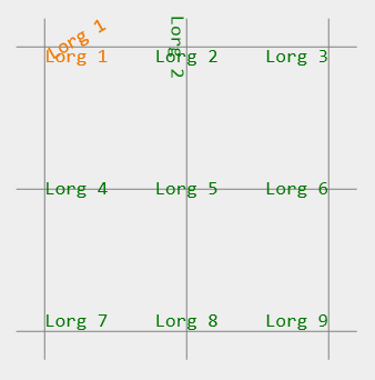
Figure 1. Placement of the 9 labels show all possible lorg values. The text drawing origin is indicated by the adjacent grid intersection.
shapeDefs3D
Cango3D makes available the shapeDefs3D object which has methods to create the Cgo3D data defining the outline path of many commonly used shapes.
Syntax:
var shapeData = shapeDefs3D.circle(d);
Description:
Generates a Cgo3D format data array defining the outline path of a circle with diameter 'd'. The returned array is suitable as input parameter for the Obj3D constructor for PATH or SHAPE types objects. The Obj3D drawing origin will be at the center of the circle.
Parameters:
d:Number - Diameter of the circle measured in the world coordinates.
Returns:
Array - Array of Cgo3D format commands and associated coordinate pairs defining the outline of the circle.
Syntax:
var shapeData = shapeDefs3D.ellipse(w, h);
Description:
Generates a Cgo3D format data array defining the outline path of a ellipse with width (X axis) 'w' and height (Y axis) 'h'. The returned array is suitable as input parameter for the Obj3D constructor for PATH or SHAPE types objects. The Obj3D drawing origin will be at the center of the ellipse.
Parameters:
w:Number - The width (X dimension) of the ellipse measured in the world coordinates.
h:Number - The height (Y dimension) of the ellipse measured in the world coordinates.
Returns:
Array - Array of Cgo3D format commands and associated coordinate pairs defining the outline of the ellipse.
Syntax:
var shapeData = shapeDefs3D.square(s);
Description:
Generates a Cgo3D format data array defining the outline path of a square with sides of length 's'. The returned array is suitable as input parameter for the Obj3D constructor for PATH or SHAPE types objects. The Obj3D drawing origin will be at the center of the square.
Parameters:
s:Number - Side length of the square measured in the world coordinates.
Returns:
Array - Array of Cgo3D format commands and associated coordinate pairs defining the outline of the square.
Syntax:
var shapeData = shapeDefs3D.triangle(s);
Description:
Generates a Cgo3D format data array defining the outline path of an equilateral triangle with sides of length 's'. The returned array is suitable as input parameter for the Obj3D constructor for PATH or SHAPE types objects. The Obj3D drawing origin will be at the center of the triangle.
Parameters:
s:Number - The length of each side of the triangle measured in the world coordinates.
Returns:
Array - Array of Cgo3D format commands and associated coordinate pairs defining the outline of the triangle.
Syntax:
var pathData = shapeDefs3D.cross(s);
Description:
Generates a Cgo3D format data array defining the outline path of a cross with horizontal and vertical arms of length 's'. The returned array is suitable as input parameter for the Obj3D constructor for PATH type object. The Obj3D drawing origin will be at the center of the cross.
Parameters:
s:Number - The length of the horizontal and vertical arms of the cross, measured in the world coordinates.
Returns:
Array - Array of Cgo3D format commands and associated coordinate pairs defining the outline of the cross.
Syntax:
var pathData = shapeDefs3D.ex(s);
Description:
Generates a Cgo3D format data array defining the outline path of a ex with arm lengths 's'. The returned array is suitable as input parameter for the Obj3D constructor for PATH type object. The Obj3D drawing origin will be at the center of the ex.
Parameters:
s:Number - The length of each arm of the ex, measured in the world coordinates.
Returns:
Array - Array of Cgo3D format commands and associated coordinate pairs defining the outline of the ex.